I recently completed my build of a Blaster 3 Spread-Tow Carbon 1.5m DLG, which is a fantastic craft. Here are some notes of the things I learned during building.
This RCGroups thread has all the build notes you could ever need, though you’ll have to read a lot of pages to find all the highlights! Particularly useful is the “view all attachments” feature, which shows all of the pictures in the thread on one page. The Hyperflight store page also has a handy list of recommended control throws.
The official manual doesn’t mention how the horns should be placed relative to the hinge line of the control surfaces. I believe they should be positioned so that the hole in the horn is directly above the hinge line.
If you’re a left-handed thrower, the rudder’s horn should also be on the left side of the craft (so it’ll effectively be hidden by the rudder when you’re holding the glider by its peg ready for launch).
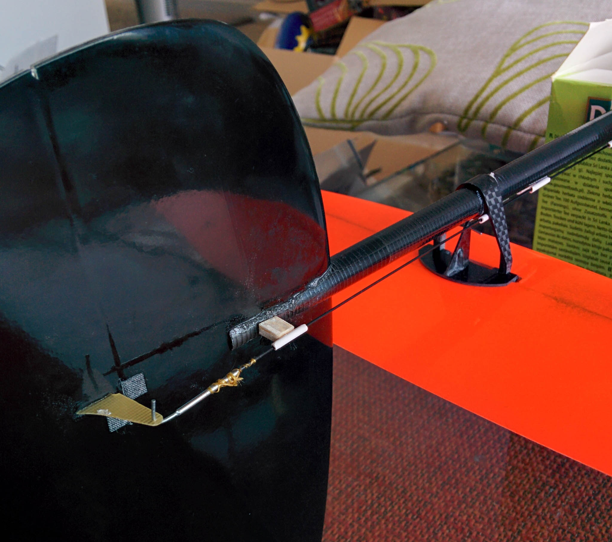
When gluing the V-mount and rudder to the tail, be sure to scuff up the surfaces first with some sandpaper, and then clean the carbon parts down with acetone to remove any leftover release agent (from the moulding process). This will ensure a secure glue. After carefully aligning the V-mount, I glued it to the boom by wicking thin CA into the crack between it and the boom. A small balsa spacer was added to align the last control rod sleeve with the rudder. I also glued the vertical stabiliser using thin CA.
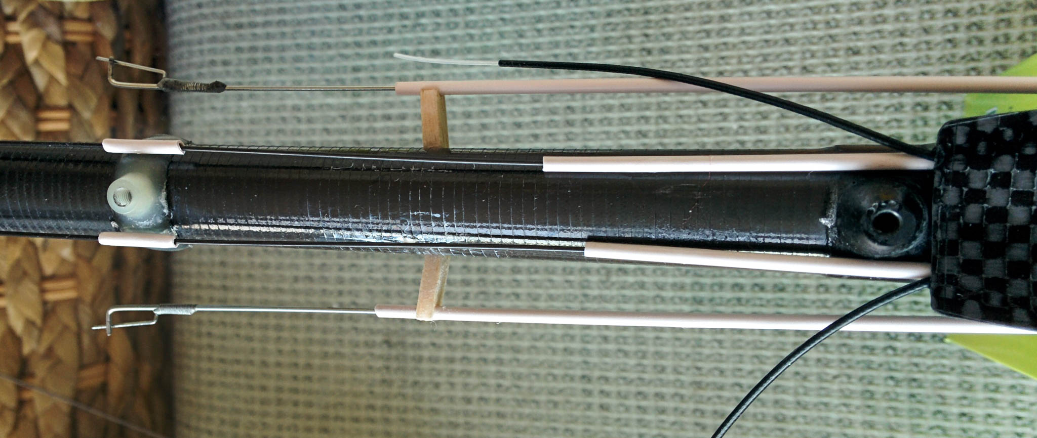
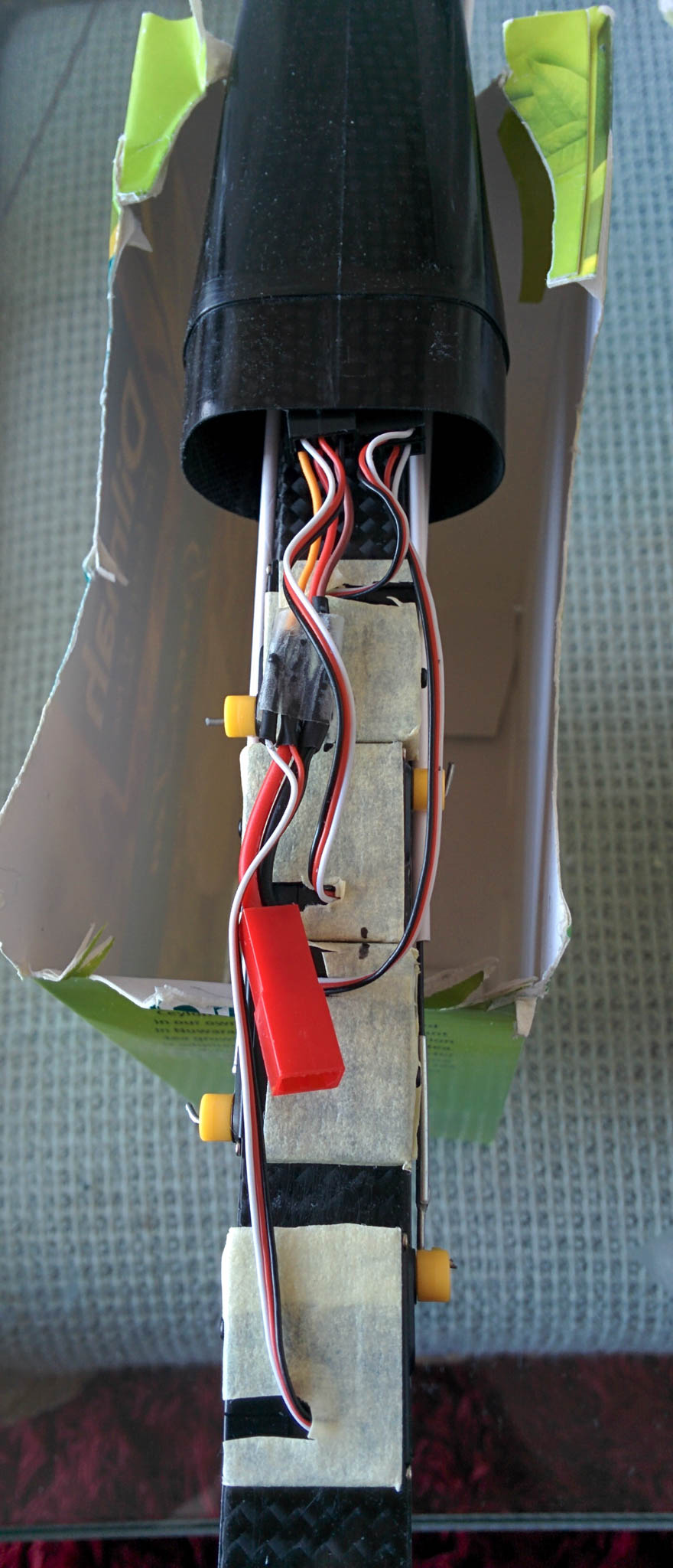
I found that the manual’s suggested aileron pushrod placement (exiting through the top of the back of the pod) required them to be ridiculously bent, and the force required to move them was too high. Instead, I drilled slots in the back of both sides of the pod (at the level of the servo arms) which allowed the aileron horns and the servos to connect together in a straight line. This also gave me more room for my antennas to exit the back of the pod alongside the rudder and elevator pushrods. A small round file can be useful in extending the drilled hole into a slot shape.
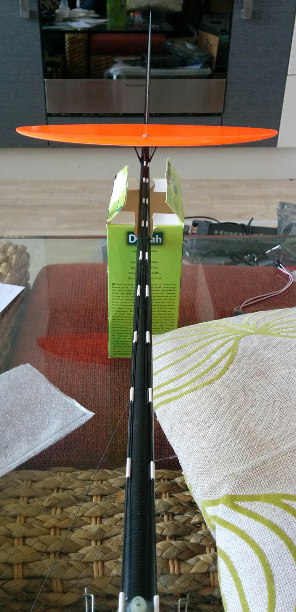
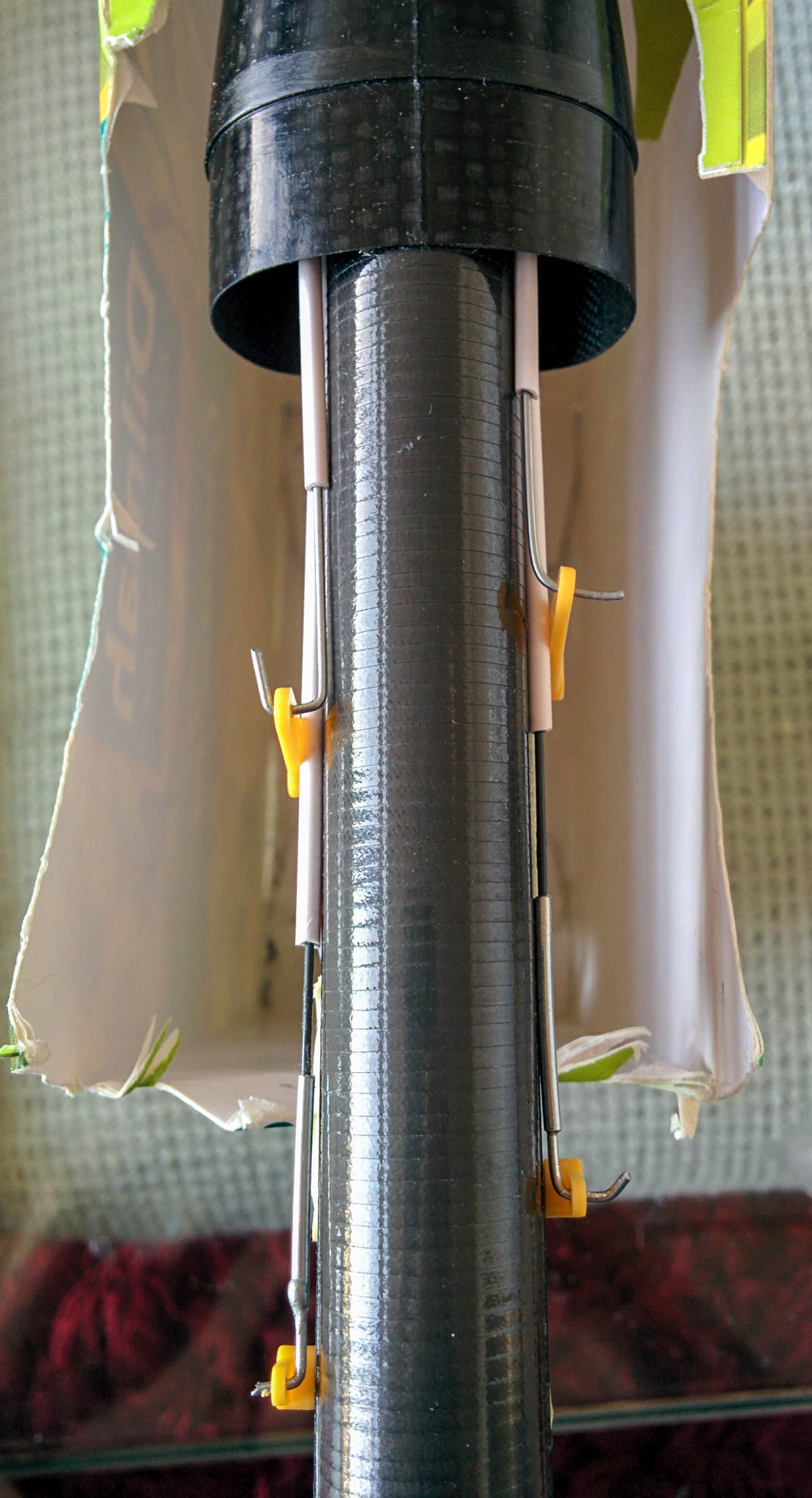
In compression, the aileron pushrods would bow near the ailerons. To fix this, I glued balsa supports between the aileron pushrod sleeves and the boom to hold them in place. By happy coincidence, these supports ended up being at the 80mm suggested CoG location, so I can use them as a CoG reference.
This is a popular modification, so there are lot of pictures of it for reference on the RCGroups thread, like this from Brain52.
When cutting the PTFE pushrod sleeving into 10mm lengths for the elevator and rudder pushrods, I found that the ends of the sleeves were getting crushed flat by the cutting action. I squeezed them in the opposite direction with a pair of pliers to bring them back to round, but the shape was still imperfect, and the friction with the pushrod was extremely high. To fix this, I slid the sleeve segments onto a piece of piano wire, and then heated them with a hair dryer. This allowed the sleeving to relax back to its former shape, and the friction dropped away to just about nothing. You’ll know if you got this right when the sleeves can slide up and down the wire on their own (under just their own weight).
If you choose your servos carefully, you can use a 2S LiPo battery to power everything. I’m using the Ripmax SD100 servos (Dymond D47 clone), which can tolerate the 8.4V of a fully-charged 2S battery. This way, you don’t need to use a voltage regulator, and FrSky telemetry-enabled receivers can transmit the actual battery voltage down to the ground without adding additional battery voltage sensors.
If you glue a servo in the wrong place, don’t worry about it, this is why you wrapped the servo in masking tape. The servo can be cleanly pulled off the tape, leaving just a square of glued tape behind on the boom, which can be removed with acetone.
Because the ailerons need such a large throw to allow for braking, I used longer arms on the aileron servos. This also allows room for the sleeves of the rudder and elevator servos to pass by within the arms of the ailerons.
I’m using the Turnigy Nano-Tech 300mAh 2S 35-70C as a battery, which is a little too tall to slide all the way to the front of the nose, so mine is mounted about 10mm further back. Because there’s so little vertical space available above the servos, the JST battery connector is a bit too thick to fit nicely above them. It works acceptably for the moment, but I plan to replace both the main connector and balance connector on the battery with a single servo connector.
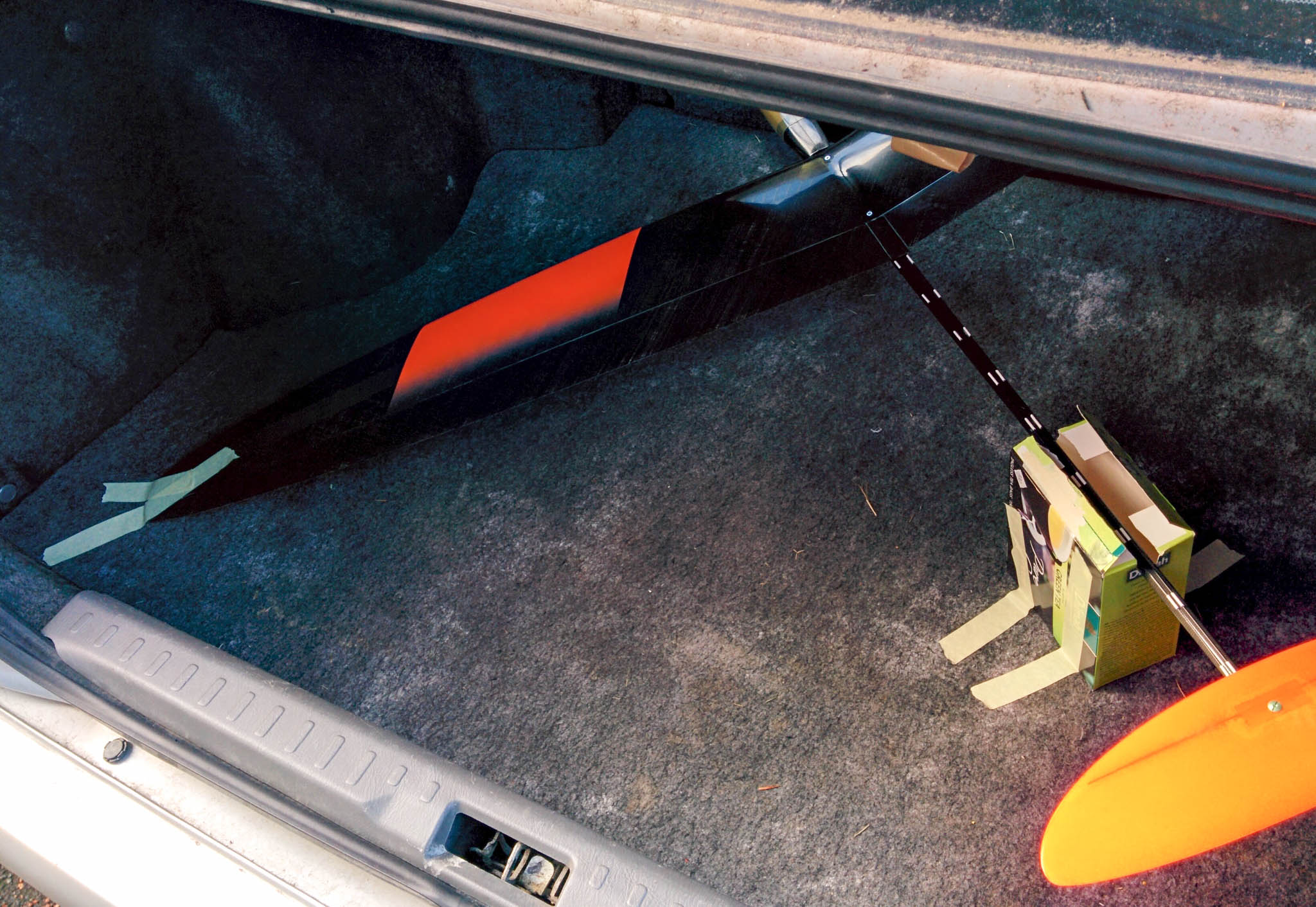
I was worried that the Blaster wouldn’t fit in my car (Nissan Primera), but it turns out that I can fit it in the boot (trunk) if I fold both back seats down. I cut a slot in the top of a small cardboard box to act as a stand to hold the tail surfaces off the floor, then used masking tape to attach the left wingtip and the nose to the carpet. This holds the glider very nicely in place while driving.